Historically it was possible to create four lane lap counting solutions with the APB C7042 by connecting additional phototransistors for panes 3 and 4 by parallel wiring them with the phototransistors already in place for lanes 1 and 2. The connections are made collector-to-coloector and emitter-to-emitter.
This approach is not possible with the ARC PRO due to the configuration of the sensors.
However, if a number of conditions are met... and the ARC PRO sensors are placed into an APB-compatibility mode, a four lane digital start/finish line can be implemented.
Requirements:
1/ the ARC PRO must be v0.4 or if v0.3 then the resistor swap-out to 510 Ohms must be carried out.
2/ the APB-compatibility modification must be carried out as per the link: https://www.slotforum.com/forums/index.php?showtopic=196039&p=2340293
3/ the lane 3 and 4 four sensors are each a pair of parallel wired VEMT2000X01 phototransistors.
4/ the four lane solution functions only with the Magic unofficial ARC app, though two lane compatibility with the Hornby ARC app is retained.
5/ race speeds while crossing the S/F line must be kept below about 4m/s (precise limit to be determined)... so avoid placing on long straights.
So first the theory... the following graphs are sensor read-outs for a car on ID6 travelling at approx 1.2-1.4m/s.
![]()
Figure 1: standard ARC PRO ID sensor readout - stay straight.
![]()
Figure 2: standard ARC PRO ID sensor readout - LC.
![]()
Figure 3: Car traversing ARC PRO ID sensor on lane 1 - stay straight - (with VEMT sensor parallel wired on lane 3).
![]()
Figure 4: Car traversing ARC PRO ID sensor on lane 1) - LC - (with VEMT sensor parallel wired on lane 3).
![]()
Figure 5: Car traversing VEMT2000X01 ID sensor on lane 3 - stay straight - (with ARC PRO sensor parallel wired on lane 1).
![]()
Figure 6: Car traversing VEMT2000X01 ID sensor on lane 3 - LC - (with ARC PRO sensor parallel wired on lane 1).
Without going into lots of technical details at this point... the graphs show the parallel wiring is functioning nicely....
C
This approach is not possible with the ARC PRO due to the configuration of the sensors.
However, if a number of conditions are met... and the ARC PRO sensors are placed into an APB-compatibility mode, a four lane digital start/finish line can be implemented.
Requirements:
1/ the ARC PRO must be v0.4 or if v0.3 then the resistor swap-out to 510 Ohms must be carried out.
2/ the APB-compatibility modification must be carried out as per the link: https://www.slotforum.com/forums/index.php?showtopic=196039&p=2340293
3/ the lane 3 and 4 four sensors are each a pair of parallel wired VEMT2000X01 phototransistors.
4/ the four lane solution functions only with the Magic unofficial ARC app, though two lane compatibility with the Hornby ARC app is retained.
5/ race speeds while crossing the S/F line must be kept below about 4m/s (precise limit to be determined)... so avoid placing on long straights.
So first the theory... the following graphs are sensor read-outs for a car on ID6 travelling at approx 1.2-1.4m/s.
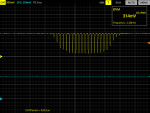
Figure 1: standard ARC PRO ID sensor readout - stay straight.

Figure 2: standard ARC PRO ID sensor readout - LC.

Figure 3: Car traversing ARC PRO ID sensor on lane 1 - stay straight - (with VEMT sensor parallel wired on lane 3).

Figure 4: Car traversing ARC PRO ID sensor on lane 1) - LC - (with VEMT sensor parallel wired on lane 3).

Figure 5: Car traversing VEMT2000X01 ID sensor on lane 3 - stay straight - (with ARC PRO sensor parallel wired on lane 1).

Figure 6: Car traversing VEMT2000X01 ID sensor on lane 3 - LC - (with ARC PRO sensor parallel wired on lane 1).
Without going into lots of technical details at this point... the graphs show the parallel wiring is functioning nicely....
C


")