SlotForum banner

Simple-H for N-Digital

25K views 29 replies 12 participants last post by  Geewiz  
#1 · (Edited by Moderator)
Ninco N-Digital has quite good power as standard, but benefits from some increased amps and a reduced volt drop under load. It also suffers from premature overloads when a full grid pulls away from the line.

The mod to multiply up on the original L6203 pioneered by Darainbow and written up by Phil and with the addition of adjustable overload protection is a good low cost solution.

http://www.slotforum.com/forums/index.php?showtopic=32634

But what if you want more current and an even lower volt drop? Well you can just keep adding additional L6203's, but beyond 2 you run out of room in the Console and for each doubling of current you have to double the number of L6203 which begins to get a bit messy.

Phil asked me for a Simple-H solution, which is now winging its way to Australia. It will be a few weeks before we hear what he thinks, in the meantime here's how to put one together for yourself.

First we need to make a few modifications to the Console.


A 3.5mm stereo jack socket is used to connect to the external Simple-H board. I mounted it in the black base of the console, below the speaker on the PCB. If mounting here drill the hole as low as possible so the speaker does not foul.

There are three connections to make.


1) Red is the data to the simple-H board connected to the tip of the jack plug
2) White is the Overload current sense connected to the centre of the jack plug
3) Black is ground connected to the rear of the jack plug.

Make the Red, White & Black connections to the PCB as shown in the above pictures. White to the lifted end of the 1K resistor.

That's it for the console; there is no need to remove the original L6203 as it is isolated from the track by the removal of the grey wires and from the overload circuit by the lifting of the resistor.

Next how to connect up the S-H board, first the input circuitry and overload pot.


Connect as follows. All connections to CN1.

Wires from the jack plug.


Red (Drive) to PA & PB
White (Overload) to CA
Black (Ground) to -

Overload Potentiometer. (1K)

White wire to CA
Other end of pot through a 120 ohm resistor to - (Ground)

Enable

The S-H board needs to be enabled; usually this would be connected to 5v, however that is not available to us so we use a potential divider.

EA has a 1.2K to + and a 5.6K to -

Finally the output circuitry.


PSU + connects to B+
PSU - connects to B-

Track Left Rail connects to B-
Track Right Rail connects to M1 linked to M2

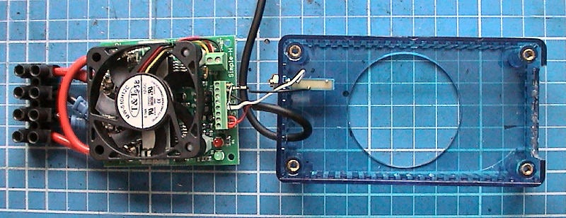
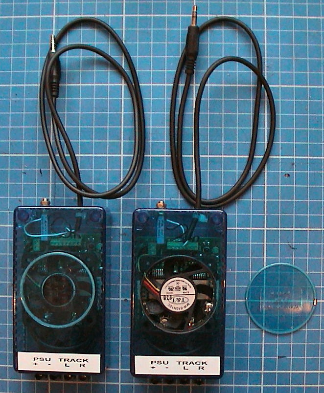
I packaged the S-H board into a polycarbonate box.


The wires are trapped in notches in the casework and screwed when the lid is screwed on. Phil's unit is fitted with a fan however I do not think it's really necessary.

All you now need to do is connect up. Wires to the PSU and the track, and the jack plug into the socket on the console.

Set the overload pot to the mid position and power up, the console can either be powered by the aftermarket PSU or the original Ninco PSU. On switching on the Red & Green Led's should light indicating that drive is present.

Overload is settable between 2.5 Amps and 30 Amps. It would probably be better to use a 500 ohm pot which would make it adjustable between 5 Amps and 30 Amps; however I am not sure how much variance there will be between units and erred on the side of caution.

Performance on the bench seems to very good. Because the Ninco system uses DC, which is just interspersed with a data burst the losses in the output stage are less than with SSD.

I tested on the bench with a continuous 30 Amps being drawn for an hour and the devices on the S-H board only reached 60 Deg C. Voltage drop is also extremely low with only 1 Volt being dropped through the board at 30 Amps.

Board is probably good for 40 Amps but I would recommend sticking to a max of 30 Amps. Overload protection uses the original Ninco circuitry fed from the current sense output of the S-H board, it seems to work well and retains the feature that on overload power is cut but then at intervals of a second or so briefly reapplied until the short is removed. This means that brief braid shorts when reslotting a car are protected against but barely noticed.

Rich
 
#3 ·
Yes that is correct Brian.

Optionally the Console could also be connected to the aftermarket PSU. My preference would be to power the console from the original Ninco PSU & S-H from the aftermarket one. This leaves you free to adjust the track voltage over a broad range without affecting the console. S-H is fine with 6 to 24 volts, however I would not go above 16 Volts as otherwise components can be damaged in the Lane Changers.

Addition to the above instructions.

Forgot to say that there is a small mod needed to the S-H board.


R5 needs to be removed. This is the onboard fixed sense resistor, that is replaced by the pot. Failure to remove this will make overload levels too high. Also check that the mini-shunts are on positions EA & CA.

Rich
 
#4 ·
THank you, Rich!
Please clarify what a S-H board is. Where can I get one so I can try out this mod?

Do you think this will help overcome the motor overheating issue with Ninco N-Digital because of having more current available and reducing the Voltage drops you mentioned?

Thanks,
Doug
 
#5 ·
The Simple-H board is available from Robot Power in the States. Originally intended as a motor controllor for Robot Wars style robots it uses a pair of BTS7960B Mosfets which were themselves originally intended for the Automotive industry for jobs like seat & wing mirror controllers. Now tried and tested in the Scalextric Powerbase.

http://www.robotpower.com/

Unfortunately it will not do anything for the Ninco Motor overheating, that needs a change to the PWM frequency and use of 100% PWM at full throttle.

Rich
 
#7 ·
This is gonna be great Rich!!
Last night I finished building the new Ninco track on the blue table,just plugged in a standard pb and 2 std ninco power supplies ,for the time being until simple h arrives.
After having gotten used to the power delivery with the triple mosfet pb on the red track ,it was interesting to go back to stock and try it.
With just 3 cars..and they were stock motored light magnet effect aussie v8's.
Power drop with 3 cars running as opposed to just one is more noticable for me now than when i first started using n digital..The power surge as a car or two came off the track is particularly noticeable..
So after having gotten so used to great power with the triple mosfet mod I'm definitely more sensetive to what is happening with the stock setup,which i thought wasnt too bad (except for those annoying ol cutouts) when I first started using N digital.
I wonder,after I have equipped both tracks with simple h..and i go back to the old triple mosfet pb..will I notice power drop off with that setup in the same way? I expect that i will for sure.
The triple mosfet mod certainly works well but I know that voltage drop under heavy load is still there..
With 8 heavy mag ,including some NSR equipped cars on the track,my psu spikes up to around 12 amps on startup and fluctuates between about 4 to 10 amps during racing..The thermo fan in the D3800 power supply runs constantly under these conditions..It is a superb PSU!!
This is going to be a great setup.
Random notes..
Overheating motors....
I had a theory that some chips were causing motors to overheat more than others..It has proved false.
I have had some bad luck with my testing..in that with the 2 cars I'm testing..first thing i did was swap motors..but after having swapped chips,they still overheat..The motors were at fault..in one case 3 motors one after the other..the 4th being ok.
This happens with a new motor immediately,if it happens to be one of the ones that doesnt like the N digital PWM delivery
Some 18k short can mabuchi's seem to be very susceptible to this problem while another identical motor will not get too hot.
While testing scorpius,I swapped out the Ninco chip on an overheating car and put in the scorpius chip..no overheating.. So this is definitely a problem with the Ninco pwm
Yet one customer has a std 18 k equipped N chipped car with extra magnet,that spanks the others in its class yet it runs significantly cooler than the others!!
I have found that the overheating prob is much less at 13.8 volts that at 15..We always run at 13.8 now simply because it makes for better racing..But turn it up to 15 and you can immediately start to smell those mabuchi's cook!.
The long can mabuchis in the F1 cars have been showing no signs of overheating.
The Ninco Nc 5's dont overheat.
The NSR motors both Shark and particularly the King motor can handle heaps of extra magnet and they dont overheat.
I have 2 customers with 21k slotit equipped cars and they get very hot.

Thoughts re the lack of data output from the pb..

In reality our club is getting by just fine without it..None are too interested in having a computer screen to watch during racing.
They say that they cant take thier eyes off the track for more than a milisecond during an 8 car race anyway..
Still I feel a good RMS would offer them more than they think at present..
The std ninco score towers do an adequate job ,but are very difficult to see..I must devise a lighting system for them.
Everybody misses the Rich G lap displays..they are superb and highly visible.
Things are changing in my shop / club..I'm selling lots of NSR motors..so the overheating issue is less important than it was when everyone used stock motors.
Raz's zener diode mod is fantastic..every open wheel car and every NSR car in the club runs it.
The copper taped rails have really settled in and the track will go 3 weeks before showing signs of needing a clean..

My wish list now...

Simple H for N digital..It's here!! Thanks Rich..you are a champion!!
A Ninco issued RMS cd carrying a field upgrade for the PB that cures arange of bad firmware problems..I'm still wishing and waiting.
A double length and properly tested double lane change piece... I'm probably just dreaming...
Phil
 
#8 ·
curious

elsewhere u have posted that u will drop ninco chips and base when scorpius arrives in spring
and that all your customers will be required to buy new
now u are praising ninco again
and saying problem was not chips but motors

wonderin how that analog expert on digital will spin that now
since he seems to base alot of his digital views on your continual posted problems
with first scaly then ninco
 
#9 ·
QUOTE (gorp @ 1 Sep 2008, 15:19) <{POST_SNAPBACK}>curious

elsewhere u have posted that u will drop ninco chips and base when scorpius arrives in spring
and that all your customers will be required to buy new
now u are praising ninco again
and saying problem was not chips but motors

wonderin how that analog expert on digital will spin that now
since he seems to base alot of his digital views on your continual posted problems
with first scaly then ninco

Get it right mate...go back..find what u think you read and qoute it!
at no time did i say That i will be dropping the Ninco Pb...
I said that no real enthusiast will bother with any of the existing systems when the scopius system is released..Im not just an enthusiast..Im a shop owner first
Scorpius will operate in my shop on the ninco tracks using the ninco pb to supply power when we are just playing...I have a quick change setup in place to go to dc power on the rails for an all scorpius class..My customers will not have to re chip..They will be free to buy scorpius chips and throttles..but those cars will belong in a new and separate class..
What I did recently was trade in everyone's ssd chip and re chip to Ninco.
Also get this right...
The PWM frequency used by Ninco as well as the lack of a 100% power dc power from the rails max throttle step is nothing less that a beginner electronics engineers mistake..It is bound to cause overheating in motors especially on tracks with long straights like mine...and it certainly does!!
My testing has revealed that some individual mabuchi motors can suffer more than others...I thought that some individual chips may cause severe overheating..I was wrong.
The issue of armature /brush timing as well as can venting has a very great bearing on this problem
Those same motors dont overheat whe using the scorpius chip that uses a very much higher PWM frequency and also has a 100% max power step..
The overheating can be lived with as long as it doesnt melt the motor mounts..sadly I have seen several cars do this.
I have never praised Ninco..In fact I have been scathing in my criticizm of them.
I recently had my distributor forward them an email from me suggesting that perhaps they should get someone other that the tea lady's son to do thier electronics development work for them..As it smacks of rank amatuerism.
If scorpius had been available when I first started my buisness .That's what i would have gone with..as far as I know..it will be still quite a while before it is commercially available.
My heavily modified Ninco sytem works very well in my commercial club environment...I have taken a very long ride on the learning curve..solving problems as i go.
When scorpius gets here I have very different plans for it..
Enormous tracks in very large venues on a mobile event based system..16 cars per race..dc power on rails..software managed race control..
Its gonna be great!
 
#10 ·
sci digital forum
last posting date 8-21
front page topic is "Questions on modifying Ninco Digital"
#2 post by u - no need for ninco powerbase with scorpious
#7 post by u - replacing ninco chips with scorpious
#10 post by u - unhappy customers expected by cost of change

n if you read my #8 sf posting again
it also states your continual posted problems first with scaly then ninco
and is shown again in the sf post #9 above
does provides material for analog jokster
 
#11 ·
I really dont think you can read!!
I re read my posts
I have not said I will be throwing out N digital..
I have said that i will not be trading in Ninco chips for scorpius as i did with ssd chips for ninco
I have said that my customers will most likely be unhappy when new guys come in and buy nothing but scorpius and they will..But I have also said that scorpius will be in its own class..
In reality ..most people will want to change over their ninco chips for scorpius..its just that much better..and they will moan about the cost..And that is not my fault.
What I am doing now is recommending to anyone who asks,that they wait for Scorpius rather than invest too heavily in Ninco or ssd.
I am in buisness right now..i have to use N digital..I cant just stop operating til scorpius arrives
N digital will continue in my shop/club until the vast majority of custmers change over voluntarily...And after that I am likely to continue using it for my mobile circuit as well as for group bookings in the shop from non club members.
I couldnt give a toss about the analogue v digital debate..I stated my opinions...
I really dont care anymore about long time slotcar racers..They can keep racing analogue forever..I hope they continue to enjoy it..
I deal with racing enthusiasts.not slotcar enthusiasts.
 
#12 ·
QUOTE (PhilR @ 1 Sep 2008, 04:25) <{POST_SNAPBACK}>....I have never praised Ninco..In fact I have been scathing in my criticizm of them.
I recently had my distributor forward them an email from me suggesting that perhaps they should get someone other that the tea lady's son to do thier electronics development work for them..As it smacks of rank amatuerism....

I love your style Phil and as you clearly have great input for Ninco I wanted to share with you the following email addresses:

ANDY COLES - NINCO EXPORT MANAGER (British native and speaks English although not sure about Australian)
acoles@ninco.com

XEVI VALVERDE - yes, the tea lady's son actually made it onto the Ninco payroll as Director de Eventos (Event Director although not sure if that title was allocated BEFORE or AFTER he became the "infamous" Ninco N Development Engineer)
Xevi speaks Catalan and Spanish (not sure about English and Australian)
xvalverde@ninco.com

GOOD LUCK NINCO as "Phil's HELL" is about to hit you "HEAD ON"

Phil's Hell © of Delta RT and TM pending as well
Upcoming priceless picture of "tea lady's son with saucer" © by Delta RT
 
#14 ·
I finished putting together a Simple-H and variable, regulated power supply set up for my track today! Boy, is it slick! I love finally being able to vary the voltage also. It was an easy, straight forward project thanks to Rich's excellent pictures and instructions- Thank you, Rich!
Doug
 
#15 ·
Mine is up and running..more reports and pics next week...
did a test to adjust the overload..i can tell you it will start 8 18k std cars plus another 8 running a range of NSr motors all at the same time!
This is a fantastic setup..Forget about the additional mosfet mod..it is redundant!
Thank you very very much Rich!!
Now I need one for the big red track and one for my littel mobile track!
Phil
 
#16 · (Edited by Moderator)
Those figure sound about right. Have just measured the starting currents for some motors & got the following. These all Scalextric digital as the Powerbase allows me to monitor and log the max current, Ninco should be similar, and if anything would expect the currents to be slightly higher.

These figures only accurate to within 1/2 Amp.

Standard 18K 1.5 Amps (Standard SSD in car chip)
NSR 22K 2.5 Amps (Slot.it in car chip)
NSR 25K 3.5 Amps ( Modified SSD in car chip, Schotkey diodes & ZXMCA16D Mosfet)
NSR 30K 4.5 Amps ( Modified SSD in car chip, Schotkey diodes & ZXMCA16D Mosfet)

So 8 18K cars would take 12 Amps
8 NSR 22K would take 20 Amps

Giving a total of 32 Amps, which I would think would be close to causing the S-H to overload as it's limit I tested at 30 Amps. However a lot depends on how long the current is taken for but I would expect to see overloads if many more NSR cars were put on the track.

S-H overload can be safely adjusted up to 40 Amps, that would need the series resistor to be reduced in value a bit. However do ensure that the overload protection is working before use, without it I have had a screwdriver glowing red hot when shorting the rails...

Rich
 
#17 · (Edited by Moderator)
Thanks Rich, my order has been confirmed by Chris Baron at Robot Power!

So now its just a waiting game (and hoping some b@stard does not seal steal it beofre it gets delivered - we often have problems with postage in South Africa!)

If any other mods come to light please keep us updated.

Thanks
John

PS:- How hard is it to include a voltage limiter to prevent the input/output voltage exceeding 16volts? (as you posted above tihs the lane changers could be damaged). My PSU is from 0-30volts and I would like to ensure that if I, or anybody else, accidently changes the output it ill not damage any part of the system
 
#19 ·
Hi John

Looks fie, I would go for the 13.5 Volt version. Only thing to be careful of would be to ensure that the unit is either boxed or tucked away somewhwere as the mains terminals are partially exposed.

Rich
 
#23 ·
Depends on exactly where you are making the measurements? There will be a drop, the key thing is not the size of the drop but how much does that drop vary with current. Remember also to measure at the terminals on the S-H board to remove any effect of volt drop in the cables which at high currents can be significant.

An important reminder that with higher numbers of cars and higher performance motors you will have to pay very close attention to power distribution with digital. All the cars are on the same lane and no point in having a good output stage if you then throw it all away in getting the power to the cars.

Measuring the drop with no load I see about 1 Volt drop, however with a 25 Amp load that drop only increases to 1.1 Volts, which is extremely good.
Image


Rich
 
#25 · (Edited by Moderator)
Here are a few minor tweeks and changes following further testing and feedback from Phil.


I have substituted the cables for terminal block, these fit nicely into a slot cut in the blue box. Also a mutiturn pot fitted to allow easier adjustment of the overload current.

I have used a 500 Ohm Pot in place of the 1K & reduced the series resistor from 120 to 100 Ohms. This allows setting of the current between 6 Amps & 35 Amps.


Here is a table showing approximate resistance V Overload level. This can be measured with a multimeter on the Jack plug before plugging into the Console, connect the multimeter between the two non-tip connections.

This enables you to set to a chosen current however I highly recommend going round the track and shorting the rails to ensure that the overload protection cuts in reliably. The Red & Green LED's will flash as long as a short is present as the unit briefly applies to power to see if the short has been removed.

If anyone else has built a unit I would be interested if these values seem accurate as it is very dependant on the circuitry in the Ninco Console. I do not know how close the tollerences are and only have one unit to test.


The removed piece of case from above the fan is stuck with circular double sided velcro to the top of the fan, which leaves a gap for the air to exit. These two units ready to send off to Phil later this week.

Rich
 
#26 ·
If you use the voltage divider to Enable SimpleH this way, you'll get aprox. 9 v on EA. The higher voltage admited to Enable it is about 5v, at higher voltages like this the S-H works but the mosfets long life couldn't be guaranteed.

I think it's better to enable SimpleH using this way:

1- Remove 1200 and 5600 ohm resistors.

2- Enable Straight using another wire from +5 v stabilized from Ninco PB to EA, then there will be 4 wires from Ninco PB to Simple-H but you're sure you always enabling correctly and in stable way. Not depending on the voltage of the third party power supply. To get +5v on Ninco PB (See picture).
Image