Ninco N-Digital has quite good power as standard, but benefits from some increased amps and a reduced volt drop under load. It also suffers from premature overloads when a full grid pulls away from the line.
The mod to multiply up on the original L6203 pioneered by Darainbow and written up by Phil and with the addition of adjustable overload protection is a good low cost solution.
http://www.slotforum.com/forums/index.php?showtopic=32634
But what if you want more current and an even lower volt drop? Well you can just keep adding additional L6203's, but beyond 2 you run out of room in the Console and for each doubling of current you have to double the number of L6203 which begins to get a bit messy.
Phil asked me for a Simple-H solution, which is now winging its way to Australia. It will be a few weeks before we hear what he thinks, in the meantime here's how to put one together for yourself.
First we need to make a few modifications to the Console.


A 3.5mm stereo jack socket is used to connect to the external Simple-H board. I mounted it in the black base of the console, below the speaker on the PCB. If mounting here drill the hole as low as possible so the speaker does not foul.
There are three connections to make.

1) Red is the data to the simple-H board connected to the tip of the jack plug
2) White is the Overload current sense connected to the centre of the jack plug
3) Black is ground connected to the rear of the jack plug.
Make the Red, White & Black connections to the PCB as shown in the above pictures. White to the lifted end of the 1K resistor.
That's it for the console; there is no need to remove the original L6203 as it is isolated from the track by the removal of the grey wires and from the overload circuit by the lifting of the resistor.
Next how to connect up the S-H board, first the input circuitry and overload pot.

Connect as follows. All connections to CN1.
Wires from the jack plug.
Red (Drive) to PA & PB
White (Overload) to CA
Black (Ground) to -
Overload Potentiometer. (1K)
White wire to CA
Other end of pot through a 120 ohm resistor to - (Ground)
Enable
The S-H board needs to be enabled; usually this would be connected to 5v, however that is not available to us so we use a potential divider.
EA has a 1.2K to + and a 5.6K to -
Finally the output circuitry.

PSU + connects to B+
PSU - connects to B-
Track Left Rail connects to B-
Track Right Rail connects to M1 linked to M2
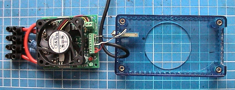
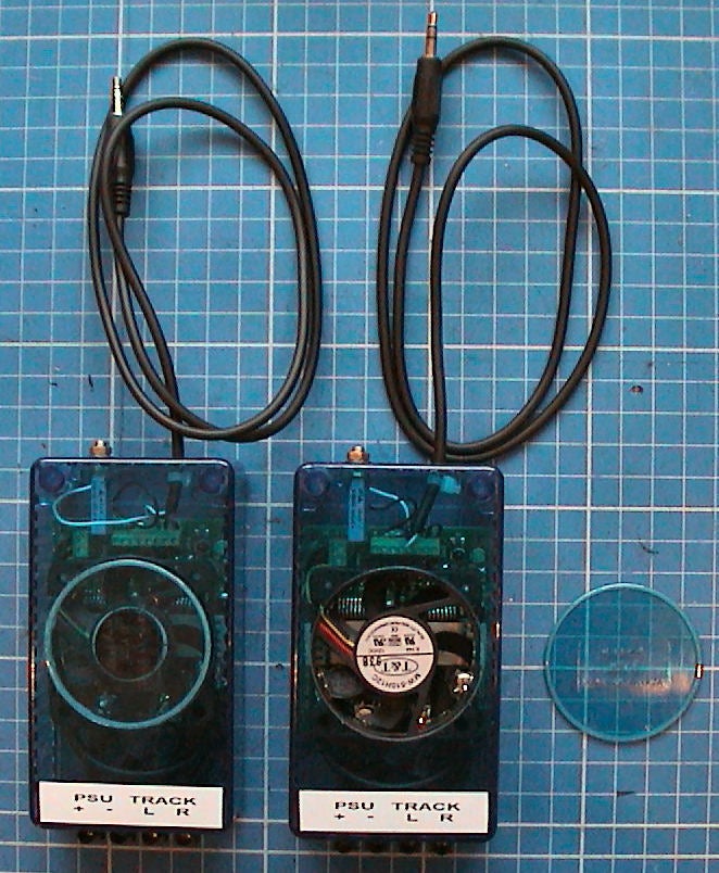
I packaged the S-H board into a polycarbonate box.

The wires are trapped in notches in the casework and screwed when the lid is screwed on. Phil's unit is fitted with a fan however I do not think it's really necessary.
All you now need to do is connect up. Wires to the PSU and the track, and the jack plug into the socket on the console.
Set the overload pot to the mid position and power up, the console can either be powered by the aftermarket PSU or the original Ninco PSU. On switching on the Red & Green Led's should light indicating that drive is present.
Overload is settable between 2.5 Amps and 30 Amps. It would probably be better to use a 500 ohm pot which would make it adjustable between 5 Amps and 30 Amps; however I am not sure how much variance there will be between units and erred on the side of caution.
Performance on the bench seems to very good. Because the Ninco system uses DC, which is just interspersed with a data burst the losses in the output stage are less than with SSD.
I tested on the bench with a continuous 30 Amps being drawn for an hour and the devices on the S-H board only reached 60 Deg C. Voltage drop is also extremely low with only 1 Volt being dropped through the board at 30 Amps.
Board is probably good for 40 Amps but I would recommend sticking to a max of 30 Amps. Overload protection uses the original Ninco circuitry fed from the current sense output of the S-H board, it seems to work well and retains the feature that on overload power is cut but then at intervals of a second or so briefly reapplied until the short is removed. This means that brief braid shorts when reslotting a car are protected against but barely noticed.
Rich
The mod to multiply up on the original L6203 pioneered by Darainbow and written up by Phil and with the addition of adjustable overload protection is a good low cost solution.
http://www.slotforum.com/forums/index.php?showtopic=32634
But what if you want more current and an even lower volt drop? Well you can just keep adding additional L6203's, but beyond 2 you run out of room in the Console and for each doubling of current you have to double the number of L6203 which begins to get a bit messy.
Phil asked me for a Simple-H solution, which is now winging its way to Australia. It will be a few weeks before we hear what he thinks, in the meantime here's how to put one together for yourself.
First we need to make a few modifications to the Console.


A 3.5mm stereo jack socket is used to connect to the external Simple-H board. I mounted it in the black base of the console, below the speaker on the PCB. If mounting here drill the hole as low as possible so the speaker does not foul.
There are three connections to make.

1) Red is the data to the simple-H board connected to the tip of the jack plug
2) White is the Overload current sense connected to the centre of the jack plug
3) Black is ground connected to the rear of the jack plug.
Make the Red, White & Black connections to the PCB as shown in the above pictures. White to the lifted end of the 1K resistor.
That's it for the console; there is no need to remove the original L6203 as it is isolated from the track by the removal of the grey wires and from the overload circuit by the lifting of the resistor.
Next how to connect up the S-H board, first the input circuitry and overload pot.

Connect as follows. All connections to CN1.
Wires from the jack plug.
Red (Drive) to PA & PB
White (Overload) to CA
Black (Ground) to -
Overload Potentiometer. (1K)
White wire to CA
Other end of pot through a 120 ohm resistor to - (Ground)
Enable
The S-H board needs to be enabled; usually this would be connected to 5v, however that is not available to us so we use a potential divider.
EA has a 1.2K to + and a 5.6K to -
Finally the output circuitry.

PSU + connects to B+
PSU - connects to B-
Track Left Rail connects to B-
Track Right Rail connects to M1 linked to M2
I packaged the S-H board into a polycarbonate box.

The wires are trapped in notches in the casework and screwed when the lid is screwed on. Phil's unit is fitted with a fan however I do not think it's really necessary.
All you now need to do is connect up. Wires to the PSU and the track, and the jack plug into the socket on the console.
Set the overload pot to the mid position and power up, the console can either be powered by the aftermarket PSU or the original Ninco PSU. On switching on the Red & Green Led's should light indicating that drive is present.
Overload is settable between 2.5 Amps and 30 Amps. It would probably be better to use a 500 ohm pot which would make it adjustable between 5 Amps and 30 Amps; however I am not sure how much variance there will be between units and erred on the side of caution.
Performance on the bench seems to very good. Because the Ninco system uses DC, which is just interspersed with a data burst the losses in the output stage are less than with SSD.
I tested on the bench with a continuous 30 Amps being drawn for an hour and the devices on the S-H board only reached 60 Deg C. Voltage drop is also extremely low with only 1 Volt being dropped through the board at 30 Amps.
Board is probably good for 40 Amps but I would recommend sticking to a max of 30 Amps. Overload protection uses the original Ninco circuitry fed from the current sense output of the S-H board, it seems to work well and retains the feature that on overload power is cut but then at intervals of a second or so briefly reapplied until the short is removed. This means that brief braid shorts when reslotting a car are protected against but barely noticed.
Rich


