SlotForum banner

Would soldering in a resistor work (7.5 Volt Artin on 12 V)?

7.9K views 24 replies 16 participants last post by  Retro 143  
#1 ·
Hey guys,

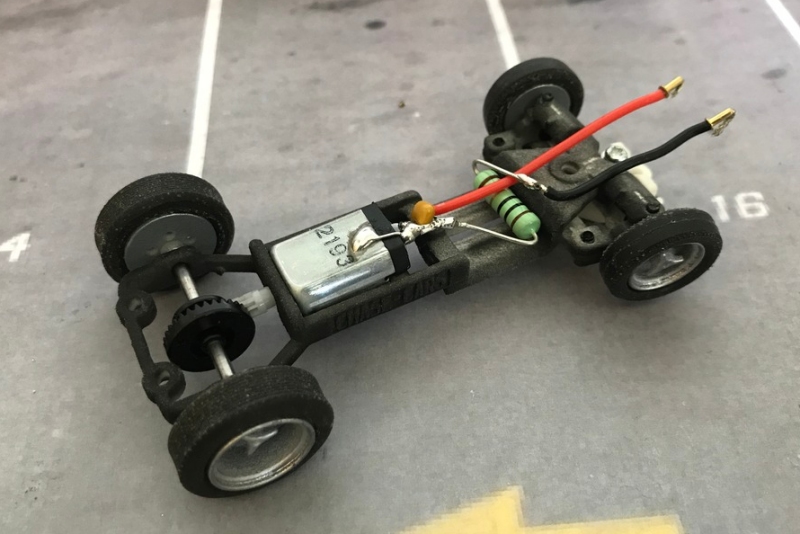
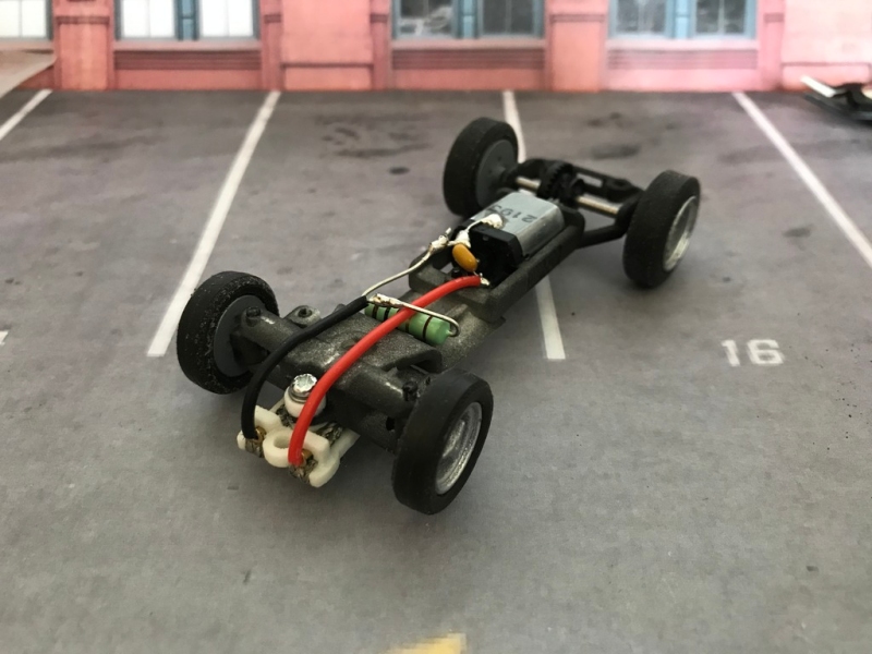
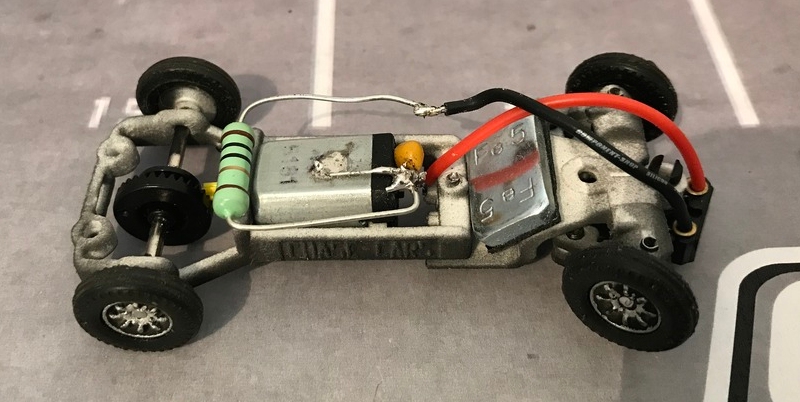
I have "converted" a few Artin/Cartronic 7.5 volt cars to 12 volts by swapping out the motor. I simply had a few standard 13D/Mabuchi motors lying around so I popped them in ( they had to go in "upside down") and rewired the motors,

I actually like the performance of this setup (with magnets) as there are some cool cars (Countach anyone?) that are not available in 1/32 and the kids love them-

The 7.5 volt motors were just too fast and and I the also made my ARC (ONE and AIR) go crazy which seems resolved with the Mabuchi and the ferritt man on them,...

Anyhoo... so I was wiring up some LEDs and mucking around with resistor values and then I thought... why can't I use resistors to get the volts down to 7.5 ?

The only thing holding me up as I do not know the "current" value in milliamps so I can't use the online calculators .I remember in the discussion last year about amps and motors we were talking about 13 amp... is that 13000 milliamps?!

The other problem is I am a complete fudgewit with math and electronics. :-D

I am a little worried about heat as there is not a lot of room in these cars...

I have a supplier for Mabuchi motors but the run about 3-5 € a piece and a resistors I can get as low as 2-3 cents. So I am curious (mind you I have to "create a ferritt man") if it would be easier/cheaper to solder in a resistor(plus the ferritt man)....

Addled minds want to know...
 
#3 ·
Resistors come in many shapes and sizes but the normal little ones are rated around 1/4 watt I believe. A 12V Mabuchi small can will run typically from 5 watts upwards.

You can probably guess what will happen to the resistor.

Yes a railway controller is one option.

Another option is to use diodes of a suitable rating. Each diode will result in a voltage drop of 0.7 volts. So if you want to reduce 12V to 7.5V you will need to daisy-chain 6 or 7 diodes to drop the voltage enough. It depend on how much room is inside the car.

Large diameter heat shrink over the daisy chain is a good idea.

Cheap rectifier diodes on eBay cost pennies each if you are prepared to wait for a slow boat from China.

The 1N5401 rectifier diode is rated as 3A and 100V and I just found some on eBay for £5.40 for 100 from Hong Kong.
 
#4 ·
5W ceramic resistors are 22mm Long by roughly 10mm square if there is enough room. Just a question of the correct resistance. Motor wattage can be found on the "Bible" site

CR5WL1.jpg
 
#6 ·
IMO diodes are a better option as they drop the voltage independent of the current draw. Each standard diode will drop the voltage around 0.7 volts.
I have been using diodes controllers with a rotary switch for years to reduce the voltage for some of the kids and drivers.
 
#7 ·
@dvd3500 - as suggested by choc-ice - i would use a resistor. normally i would simply drop the voltage of the track, but as you are using a ARC (one and air, whatever this is, i guess something digital???) - a resistor seems to be a good try to calm the artin motors. yes, the countach is nice, so is the Diablo they made :)

i think that a 2W resistor will be more than enough for that kind of slotracing.

btw. i measured 1.6A @ 12V for those artin motors - but this is a peak value only valid for a small part of a second.

@choc-ice - that Mini chassis is for a 1/43rd Mini or for a 1/32nd? looks very interesting!
 
#8 · (Edited by Moderator)
As has been said, diodes rather than resistors are probably a better solution.

If you use a chain of large diodes mounted at the power supply end you can reduce the voltage to all the cars to 7.5 ish volts. This gets away from the problem of finding space in the car for resistors/ diodes that get hot.

Resistors shared between cars give major problems, so the resistors need to be somewhere in the circuit for each car. (Either in the car or in analogue they can be in the power feed to each lane.)

Resistors in the cars will make them slower and reduce the current draw, I'm guessing that's what you really want(???) I'll briefly answer a couple of questions

. why can't I use resistors to get the volts down to 7.5 ?

The only thing holding me up as I do not know the "current" value in milliamps so I can't use the online calculators .I remember in the discussion last year about amps and motors we were talking about 13 amp... is that 13000 milliamps?!
You could find a resistor that gives 7.5 volts for that motor at one motor speed. That will give you less than 7.5 volts at low speed and when staring from rest and more than 7.5 volts at full speed.

Indeed there are motor that take 13 amps (yes that is 13000 milliamps) used in quicker 1/32 cars, but the motors normally used in digital and plastic chassis type 1/32s generally take much less current. For example a Scalex S can type motor will take just over 2 amps for a very brief period when starting from rest going down to a few tenths of an amp at maximum speed. That's the sort of motor the Scalex power bases are intended for.
 
#9 ·
Very good post 300SLR and that really explains to me why it wouldn't be practical.

I was pondering something similar with HO cars as some of the N20 motors being sourced for the SL2 3D printed chassis are not going to last long at 18 volts but will be fine at 12 volts. But it would be nice to be able to race this chassis against a regular HO car. Having a variable power supply per lane would ensure each car runs at its preferred voltage for a true test.
 
#10 ·
As said elsewhere in the post, diodes are probably more efficient but you'll need a few to get down to the voltage you need. Can they be on the track supply or must they be in the car? I needed mine in the car as I didn't want to get into a separate supply for each lane and some of my cars need all the voltage they can get.

@dvd3500 - as suggested by choc-ice - I would use a resistor. normally I would simply drop the voltage of the track, but as you are using a ARC (one and air, whatever this is, I guess something digital???) - a resistor seems to be a good try to calm the artin motors. yes, the countach is nice, so is the Diablo they made
smile.png


I think that a 2W resistor will be more than enough for that kind of slotracing.

btw. I measured 1.6A @ 12V for those artin motors - but this is a peak value only valid for a small part of a second.

@choc-ice - that Mini chassis is for a 1/43rd Mini or for a 1/32nd? looks very interesting!
It's for a 1:32 Mini although it will fit in some narrower 1:43 cars. The wheelbase is adjustable and the steering is available in different widths, scale drawings are here and here
 
#11 ·
I don't have much time so first and foremost: Thanks for all the ideas!

There is very very little space in the cars as the 13D/Mabuchi size literally take up almost all the interior and wedge type cars have very little room under the hood or trunk.

I do not want anything on the powerbase side because ARC AIR (https://www.scalextric.com/uk-en/shop/sets/app-race-control-arc/arc-air.html ) likely won't like it.

ARC ONE could be able to handle it as you can separate the powerbase (I tend to use dimmers to regulate power down).

Ideally the cars would have the power mod so that if I am not around they can run things on their own.

While diodes sound better in theory I am thinking resistors might have to do the trick as space is a problem and I am flipstick with electronics... :-D

No I just have to figure out how to also add a "ferritt man" to keep ARC from freaking out..
 
#13 ·
just read this so a very late reply but it may prove useful.

There are, I think, 6 options but only 2 will work if you can't or don't want to switch power supplies or controllers.

1) Use a lower voltage power supply such as the Artin one which is 7.5 volts.

2) use a variable voltage power suppy. Cheapest options are an old train controller, I would go for a Triang P6 as it has a useful high/low switch or a switchable voltage universal power pack as you can normally set the voltage in 1.5v steps.

3) Use Carrera Go controllers which restrict the voltage until the turbo button is pressed, you can disable the use of this button. I think SCX Compact controllers work the same way,

4) Make a custom controllerby finding some way to restrict the trigger/plunger movement so the controller works like the Go ones but you decide the cut-off point.

The next 2 options all need some soldering skills

5) The resistor option. yes you can put a resistor between controller and track but the results will be different for each car. This is because in this situation the voltage will depend on how many amps the motor is drawing (Voltage = amps x resistance). This means that for the best results the resistor needs to be matched to the motor and fixed in the car.

6) Use diodes as stepped voltage droppers. The best method is to use a 10 or 12 way rotary switch, depending on the input voltage 10 way will give upto a 7 volt drop and 12 way 8.4 volts, for each lane. You wire the input supply to the first terminal and then wire the diodes between each terminal and the output to track come from the wiper. This way you can adjust the voltage on each lane in approximately 0.7 volt steps to suit each motor or the racer, it also allows you to have even racing with total different cars.

I think option 6 is the best choice as it allows for so many variables and was what I intended to use on my routed layout. This would have allowed me to evenly run my slowest Jouef cars against the faster Go, Compact and D-Slot cars. It also allowed me to use my digital Ninco controller that needs a least a 12 volt input to work.
 
#14 ·
Rather than put resistors or diodes in the cars you can put them in the controller circuit. If a resistor is in the car your brakes will also be reduced, if diodes are in the car you will have no dynamic braking at all. I sometimes race overpowered HO cars and I built a "choke box" to reduce the voltage with those.

31880671934_ee84561db4_o.jpg


If your cars are hard to drive the best solution is probably to use a variable power supply. A variable voltage regulator like this one can also be used to reduce the track voltage.
https://drive.google.com/open?id=0BzLR42NthGeCNDQxNGQwMWUtMDExNC00ZTJlLTk0NDMtYTk4YTA3NjdjNTZh
 
#15 · (Edited by Moderator)
Actually not for 1:43 but the thread seems relevant and i suppose this kind of question is universal... I am waiting for the weather to improve to try to decide how best to implement resistors and diodes

I have built a simple ladder circuit which will allow my control computer to switch in and out diodes and resistors from my power circuit.

I have

Rectifier Diodes (0.7V drop I expect)

Schottkey diodes (0.25-0.45V drop)

Resistors

11 rectifiers reduces the voltage enough that cars barely make it around the circuit but I'm not sure how best to do it

I was kind of thinking the first 5 could be schottkey, then 5 resistors then 5 rectifiers

But I'm not sure how diodes and resistors will affect things. Will there be a difference in the way a car responds to resistors and diodes?

hich would be the best for simulating a change in fuel load?

I guess the rectifiers will slow it down so much I'll use them to be the tyres going off badly

Any ideas?
 
#16 ·
Your best bet is to try the component you already have to get the amount of slowing you want. Just connect them up using a screw terminal block then you can swap them quickly and test several combinations.

Assuming the components have adequate current rating, a Schottky diode will drop about half the voltage of a normal diode, so you only need one Schottky (For example 1 ordinary diode gives about twice the drop of a Schottky, 1 ordinary diode + one Schottky gives about 3 times drop of a Schottky)

We'd need to know the resistor values and what sort of motors you are using to predict how your resistors will affect things
 
#17 ·
Lots of people suggesting changes supply/controllerside. This isn't practical with a digital system as you'd be limiting things that are meant to work on 12V as well as the 7.5V cars that are meant to work on 7.5V.

Diodes will give a consistent voltage drop but if you place them between the motor and chip you'll lose braking, and you might not be able to place them between the guide and chip because it might need 12V to operate properly.

Resistors between the motor and chip will drop more volts when current is higher, so harsh acceleration will be dampened significantly while top end will be less significantly affected (but it will be a bit).
 
#18 ·
ARC AIR/ONE are analogue not digital in terms of track voltage. However you can't mess with the input side of the power as you will indeed mess up the electronics for wireless throttles (AIR) , bluetooth, track sensors etc..

You can however very easily intercept the analogue track power output between the ARC base and the lanes themselves. I have RC controlled relays in mine to allow RC to enable/disable as required.
 
#20 ·
Your best bet is to try the component you already have to get the amount of slowing you want. Just connect them up using a screw terminal block then you can swap them quickly and test several combinations.

Assuming the components have adequate current rating, a Schottky diode will drop about half the voltage of a normal diode, so you only need one Schottky (For example 1 ordinary diode gives about twice the drop of a Schottky, 1 ordinary diode + one Schottky gives about 3 times drop of a Schottky)

We'd need to know the resistor values and what sort of motors you are using to predict how your resistors will affect things
You red my mind i have a ladder build with chocolate blocks. Just waiting on the weather to improve before i go back out to the 'racing room' or shed as it's more commonly known.

I'll start messing about with the best combination then.
 
#21 ·
We'd need to know the resistor values and what sort of motors you are using to predict how your resistors will affect things
True... the motors tend not to have any markings on them so a bit tough...

I have a few other projects in line first but I will come back to this!
 
#22 ·
"... the motors tend not to have any markings on them..."

Tell us what you can about your motors - the collective wisdom on SF might well give some useful answers.

Alternatively try testing your motors with a resistor and see what happens. It's unlikely to do any harm. If it's too slow or too fast that'll point in the right direction for a lower or higher value resistor.
 
#24 ·
A resistor drops voltage proportionally to the amount of current going through it. The current will tend to vary somewhat depending on the motor itself and also whether the car is accelerating or has reached top speed. If you us a conventional resistor controller that will see the same effect.
 
#25 ·
I haven't read this whole thread, but here's what I find works extremely well for me.
I run a small Artin 1/32 scale 4 lane figure 8.
I use standard Carrera Evolution 1/32 power and control. I've cut into one of the power supply to track wires and wired in a variable potentiometer of 0-100ohms.
This allows me to run 1/32 and 1/43 cars non magnet.
For 6 volt Mabucci type cans, I set the potentiometer to ~15ohm (I have a little digital ohm meter also wired in. In my opinion this works way better than series of diodes if you wish to retain standard controllers... Otherwise you'll need either variable sensitivity controllers or a selection of different ohm rated controllers to suit your various cars.
I tried both 100ohm 25watt variable potentiometer and my preference is actually larger 100ohm 100watt as these allow me to easily step 1ohm at a time.
The reason I went chose 100 ohm was all about availability. I couldn't find 50ohm with a high enough wattage rating.
I do this on each lane, so it allows me to even up performance of different cars and drivers.