For my next project on my 3D printer, I would like to try making a flipped curve I.e., an inside-out banked curve I.e., a 10 degree off-camber curve.
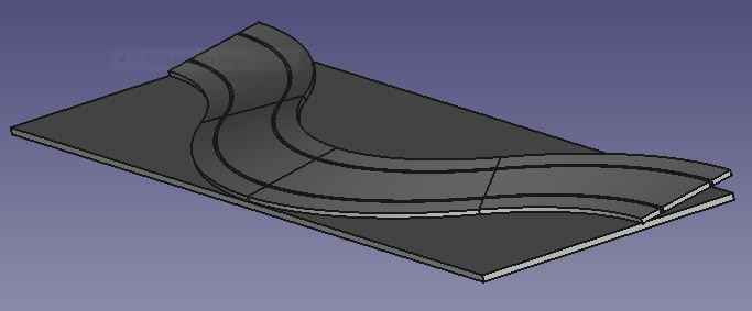
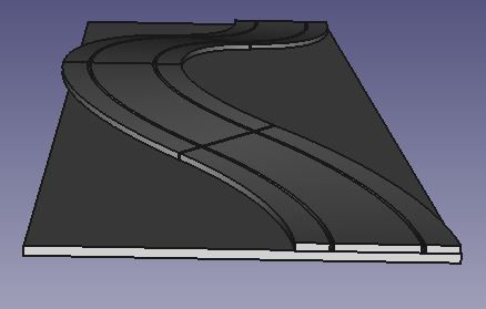
Below is a CAD model of two flipped curves flanked by two ordinary Scalextric R3 banked curves. All four curves are sitting at 10 degrees to the table. I have to admit that, in terms of slot cars performing on track, it looks like a recipe for misery, not fun.
![Image]()
![Image]()
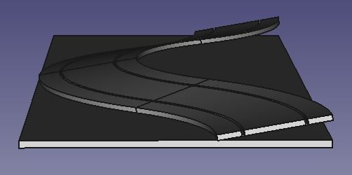
However, if you tilt the assembly 10 degrees so that the leading edges are horizontal, you get this:
![Image]()
![Image]()
![Image]()
The beginning, middle, and end are horizontal, and you get a nice "up and down and around the hill" effect. Halfway up the hill and halfway down the hill you get a 3 degree off-camber. The really nice thing about this is that it's smooth - all the geometry is right - no clunky segmentation like if you tried this with flat R3 curves. I think it will be a lot of fun to drive on with borders both sides and magless cars. I have started trying to figure out sizes and shapes and how I could 3D print them.
Any thoughts?
Below is a CAD model of two flipped curves flanked by two ordinary Scalextric R3 banked curves. All four curves are sitting at 10 degrees to the table. I have to admit that, in terms of slot cars performing on track, it looks like a recipe for misery, not fun.
However, if you tilt the assembly 10 degrees so that the leading edges are horizontal, you get this:
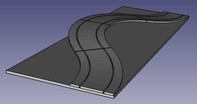
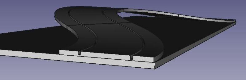
The beginning, middle, and end are horizontal, and you get a nice "up and down and around the hill" effect. Halfway up the hill and halfway down the hill you get a 3 degree off-camber. The really nice thing about this is that it's smooth - all the geometry is right - no clunky segmentation like if you tried this with flat R3 curves. I think it will be a lot of fun to drive on with borders both sides and magless cars. I have started trying to figure out sizes and shapes and how I could 3D print them.
Any thoughts?