SlotForum banner

The Bourne Raceway

128K views 610 replies 51 participants last post by  SlotNewbie 1  
#1 · (Edited by Moderator)
Hi everybody!

I've been a reader of the forums for a while but this is the first time I've actually signed up and decided to post.

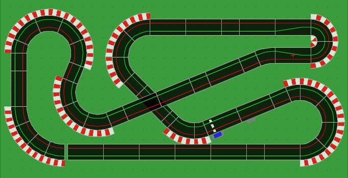
My company has arranged a session at a local slot racing place for everyone to spend a couple of hours racing as a Christmas group activity. Not everyone at work has raced slot cars before so I thought I'd dig my collection of Scalextric out of the shed and build a track in the office for people to practice on. I originally wanted to reproduce the Farrout Raceway, I had all the parts but it was just too big a track. So I decided to try and copy the excellent Flying Cow Raceway instead.

The original plan was a 4 lane Scalextric version as below but the room we used in the office wasn't quite big enough (it was deemed we needed to be able to close the door which got in the way of the first turn!).
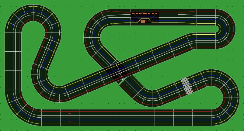
FlyingCow4Lane.jpg


So we made a few alterations and ended up with this layout.
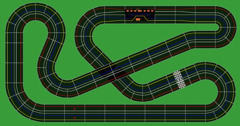
FlyingCowRestricted.jpg


It's really good fun to race on, has some very tricky corners for our 1990's cars with weak magnets. It's classic track with back to back 4 lane goodwood chicane, we have Sport multilane power and RMS so we use a laptop and a 32" TV screen to run YASCART for lap timing and races. Currently the best lap time with a 1990's Jaguar XJ220 is about 9 seconds.
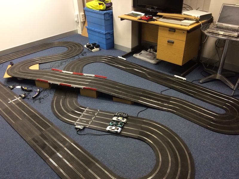
FlyingCowOffice.jpg


The photo is a little old, the room was still a mess, the bridge supports weren't finished and the second Goodwood Chicane hadn't arrived when I took it.

I fear after Christmas we will have to take the track up as its too big
sad.gif
So I was thinking of trying to make a smaller version of the layout, using all sport track, with the idea of possibly going digital at a later point. I could possibly mount this on a board that could be lifted up and rested against a wall when not in use (the room is usually used for playing four player Wii tennis).

I came up with this layout…

FlyingCowSport.jpg


I'm worried it will be a little tame compared to the original track, but I guess there isn't much I can do about that.

The question for you guys is, from your experience, how should I alter this track for the best digital experience? Do you have any suggestions on how it can be improved?

I would also like to be able to continue to race analogue with a lap timer as some people like to spend time trying to beat other peoples best lap times rather than taking part in races.

Thanks in advance for your ideas and feedback.

FD
 
#3 ·
Thanks CMOTD

Yes, that's the one, Jim Butt's track looks amazing. Someone on this forum posted a diagram of a Scalextric version of it. Unfortunately it had a lot of R4 curves which are hard to find and expensive so I changed most of them (except the entrance to the long straight) to R3 curves and ended up with our current 4 lane design.

Our version is great to race on, I can only imagine how good Jim's original is!

I read someone that Jim originally made the Flying Cow in classic Scalextric plastic before he created the wooden track, do you know where there are any pictures of his original classic Scalextric version?
 
#4 · (Edited by Moderator)
Yes it is a great track - oh to have USA size basements! I have had the good fortune to be Jim's guest on a couple of occasions and hope to visit again some time. There is another similar track in Chambersburg PA LINK

Ecurie Martini on this forum has raced at the Flying Cow and may have some information. Jim is also a member but doesn't visit very often so I will email him and ask about any previous plastic version for you.
 
#5 ·
Thanks for doing that.

The Chambersburg track also looks really good, I'm with you, why don't British houses have big basements?!!

I don't have much in the way of Sport track so I've started purchasing the rarer pieces I need on eBay today so hopefully in the new year I can setup my 2 lane design.

I think this evening I'll have a go at trying to workout where the lane changers should go on a digital version and also trying to design a future 3rd lane and a pit area. (Bit difficult as I only have Tracker 2000 and Photoshop to use for designing)

I guess that's where I could do with the help and ideas for the digital people on the forum!

Cheers

FD
 
#7 ·
That sounds like my idea of hell... I'd definitely be 'sick' that day.

We are off to Pit Slot Racing in Guildford, Surrey (UK) for a couple of hours racing. No idea what it's like! http://www.pitslotracing.com/
 
#8 ·
Hello FishyDelishy, and CMOTD

Thanks for the kind words about my track, Flying Cow Raceway. As you have found, it was the culmination of a succession of plastic tracks. With each version, I kept the bits I enjoyed, and replaced the rest. This went on for a number of years until I had what felt just right to me. When I decided to go routed wood, I basically replicated the last version of the plastic track, with the exception of tweaking the turn radii and angles to better suit the space.

So, as requested, here are a few pics of the final version in Scalextric classic track.

Image


Image


Image


With kind regards,

Jim
 
#9 ·
Hi Jim

Thanks for posting the photos of the Scalextric version of the track, once you see the number of pieces it really hits home how huge the track is, I wish I had the space to build something that big.

We had a great session on our current track inspired by your design today, had 10-15 people many who have never raced before and they had great time.

I'm busy trying to design a small digital version which I'll post up tomorrow to see what people think.

Thanks again

FD
 
#10 · (Edited by Moderator)
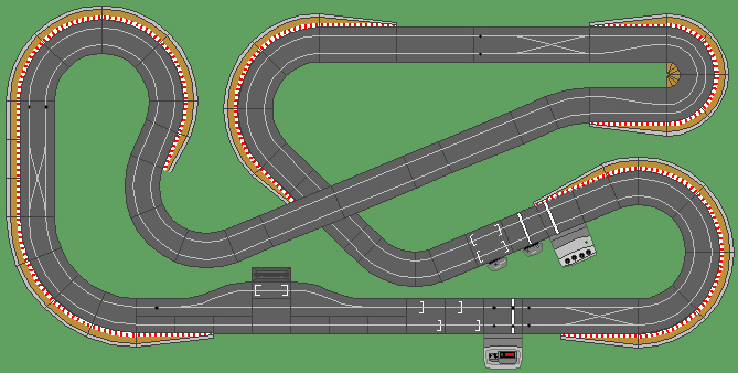
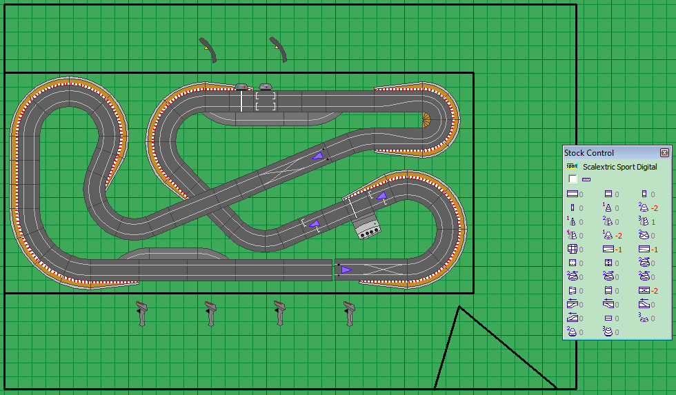
So, after a lot of thought and Photoshop work I've come up with my smaller 2 lane Scalextric Digital version of the Flying Cow Raceway.

DigitalCow.jpg


I've tried to make it usable for both analogue and digital by putting an analogue RMS and power base in the short straight after turn 1, this is where our start finish line is on the 4 lane circuit. I've also put a digital power base here for convenience. Also we race anticlockwise so it means the power and RMS units are facing the correct direction here.

I assume if you only plug one power base into the mains at any one time you can simply use analogue or digital??

I've then placed the 4 player digital lap counter and our digital starting grid on the main straight. Would I be right in saying the digital lap counter can handle cars passing over it in the wrong direction (as I assume normal operation is clockwise not anticlockwise)?

I'm slightly concerned about the lane sensor after turn 7 but I felt I had to put one here so you can get into the left lane for the pits. My thinking is if you want to pit it's up to your not to drift the bend and miss the sensor!

Anyone comments or suggestions on improvements would be very welcome.

Thanks

FD
 
#11 ·
QUOTE (FishyDelishy @ 11 Dec 2014, 22:29) <{POST_SNAPBACK}>We are off to Pit Slot Racing in Guildford, Surrey (UK) for a couple of hours racing. No idea what it's like!

It would be interesting to know what you thought of it, FD. I had never heard of it before you linked to it.
 
#12 ·
I hadn't heard of it before either. All I know is it's an 8 lane Ninco track in the Spectrum. I think there are 15 of us going on Wednesday, I'll let you know what it's like afterwards.
 
#13 · (Edited by Moderator)
Looks good! Only a couple of suggestions:
- if you are going for the Advanced Power Base (APB), it will supports both digital and analog (not at the same time), plus you can set it to run in either directions. You do not need the other power base and the lap counter as this will be done by the APB also in analog mode.
- if you are going to use it mainly in digital, then get rid of the squeeze: with the XCLs there is already enough interaction between cars so you do not need the squeeze. A lot of us have removed these pieces from our layouts because in the end they do not add much.
- each corner has the same radius (either R1, R2, or R3): I would suggest to combine different radii to give a more character to each corner.
- in the fly-over straight I would also put a XCL: it looks like an interesting point where to make a move to take over.
- I see that you are planning to have the pit-lane game there: consider that out of the box is just a game that has nothing to do with real pit strategies. My suggestion here is to buy a cable to connect the APB to a pc/laptop and getting one of the race management systems out there (my favourite one is RCS64). The level of realism of these systems will increase if you put some sensing device in the pit lane. You can either buy the pit lane game from scaley and get it modified to work with these systems. Or go for the SmartSensor, an arduino based solution that out of the box will provide all the required functionality for real pit strategies. In the end the SmartSensor will cost you less then the pit game and the required mod.

good luck!
 
#14 · (Edited by Moderator)
Hi Grunz

Thanks for your comments.

- I'd love the APB but it looks like I can't get one for less than ÂŁ100 where as I can pick up a 4 lane power unit for around ÂŁ10. My budget is quite tight as I am planning to buy all new sport track and will need lots of lane changers, new cars etc. So, for now I'm planning on the 4 car power base, I am assuming that isn't capable of reverse direction?

- Without the APB I think there will be a reasonable amount of analogue use, mainly because people in the office like trying to beat each others fastest laps. I put the squeeze in because people love the current Goodwood chicane and I thought it would keep the inside lane away from the edge of the track.

- Interesting point about the corner radius, I like the current flow so much I'm loathed to change the corners, however perhaps I could replace the squeeze with a R2, R1, R1, R2 combo. I'll see if I can fit that in.

- Does the straight lane changer need to be on a flat or down hill section? I was worried on the uphill stretch with speed the cars will de-slot.

- Thanks for the tip on the pit lane, I'll start reading up on that!

Cheers

FD
 
#15 ·
if you are on a tight budget then a lot of my comments might not apply.
As for the XCL in/decline profile, I think that it does not matter much. In my layout, one of the XCL is after a 180 R3 banked section (here is a link to the layout). So it is not laying completely flat and so far no issue at all. If you put it in the up/downhill section should be not a problem. I would put it at the beginning after the first half straight.
I just realised that the XCLs on the far left (before the last corner) the pit lane entrance are right after a corner: this is not ideal as the cars (especially mag-less) will not be straight and might miss the sensor. You have to allow for at a least a half straight before placing a lane-change piece.

For the main straight, you could move the pit lane a half-straight on the right and putting the starting grid piece in place of the half straight next to the pitlane sensor (between the single change lane). Usually you do not want the starting gird pieces one next the other. Spacing them with allow for a smoother start without collisions. For the XCL before the last corner I cannot see a solution right now...either you leave as it is and then rely on the drivers to slow down before the corner to make sure that the cars are not drifting too much or move it to another place if you cannot make the base a half-straight wider.
 
#16 · (Edited by Moderator)
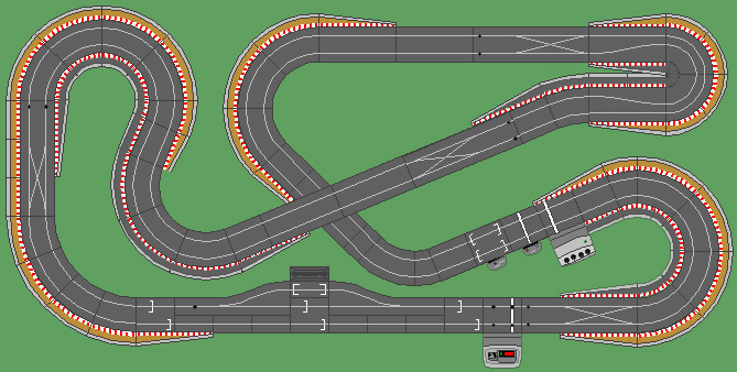
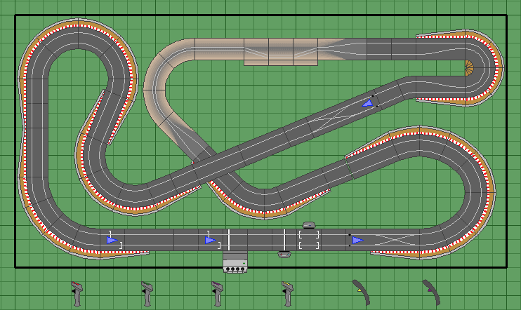
Hadn't thought of the main straight change, I've moved everything right and equally spaced three start straights, one day when I can afford a APB it could replace the lapcounter at the end of the main straight and we could use all six grid slots. So I've now come up with this...

DigitalCow1.jpg


I can't find a way to solve the final lane changer issue, I think it will have to be the drivers responsibility to make the changer safely if they want to pit, guess it adds to the challenge.

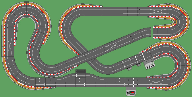
I also tried to redesign the hair pin to remove the side swipes and R1 chicane curves and came up with the following.... not sure which I prefer.

DigitalCow2.jpg
 
#608 · (Edited by Moderator)
Hi there I am new to the forum and keen to build this track. I have measured the length via track sizes used and then some approximation to be 3.425metres whilst the width seems to be more than 2meters? The original post of this track design stated its 3.5m long by 1.5metres. Can anyone help? I am building for my boy to have some extra activity during covid lockdown.
thanks in advance
 
#17 ·
Hi Fishy,

Great choice in tracks to model! Flying Cow is my all-time fav, too. I was lucky enough to race on it 7 years ago but then moved half a continent away. Here is a track plan I did after experiencing the routed track. It is not official - not from Jim - but it was fun to do. Note the R1 45 on the inside of the top hairpin. It felt that tight and tricky in real life to me.

Image


Flying Cow is 8 x 20 ft. My layout is 6 by 12 so I lost the right angle turns at the left side of the layout in favor of longer straights.

Image


For your plan, you will probably want to get rid of the xlc on the left side of the layout, it is too near the turn. Cars will slide and miss the sensors. For racing I like to have borders on all the turns. If fitting a pit lane in is a problem, don't forget you can always saw one lane off of curved track pieces. I saw the inside lane off of R1s to make the exit of my pit lane. If you possibly can, get the APB, it is worth it.

Merry Christmas, Happy 4th night of Hanukkah!
Paul
 
#18 ·
Hi Paul

Thanks for your reply & track plans. I wish I had a room big enough to do a full size replica of the Flying Cow.

However, had some great news on Friday, the Managing Director of the company has given me a spare meeting room at work to turn into a Scalextric room!! How cool is that.

The room is approximately 4.15m x 3.3m , that's about 13.5ft x 11ft. There is currently two desks and 4 filing cabinets in e room but we should be able to move the cabinets out. We can also use spare desks, sets of drawers etc for our table. So the plan is to put furniture in the middle of the room and put plywood sheets on top as our base.

I'm thinking at the moment the table will be 3.2m x 1.6m so there is room to get around it.

The APB is the long term goal but I just can't afford it at the moment. I need to sort out the other track & lane changers first. Once it's up and running I'll start selling the classic track to pay for this new venture.

I'll post a new track design up a bit later!
 
#20 ·
I don't think I have much more room to expand on my original plan, if I have its width rather than length when ideally I could do with more length to the track. If I can get rid of the filing cabinets we have a decent space to play with.

It raises a good question, if you place a table/board directly in the middle of a rectangular room how much space would you recommend is left around all 4 sides?
 
#21 · (Edited by Moderator)
So here's my current plan.

FlyingCowHybrid.png


It's a hybrid track. On one side there is a digital 4 car power base. On the other side an analogue power base and RMS. This can be used by people who like trying to set fastest laps in our 1990's Jags.

The digital aspect is experimental to begin with. Hopefully we can upgrade to the APB at some point.

I'm running very low on funds now. I still need to buy 2 lane changers, the hairpin section, some cars and DPR modules, the plywood for the base and foam board to make borders.

Anyone want to buy a big selection of classic track? Need to fund this new and expensive project!
smile.gif


EDIT: Oh forgot to say, I've tried to illustrate the room size and the door into the room. Also I was thinking of cutting up some old classic track to make a decorative pit lane, mainly somewhere to store cars when they are not being used. At the moment I don't see the benefit of a working pit lane.
 
#22 · (Edited by Moderator)
So, we are almost ready to start building the new circuit. I'm going on holiday for a week and I'm promised when I get back the office/meeting room will be emptied of furniture so we can get started. I think I have all the track for the initial build. Still lacking cars at the moment though.

Having been laying out some track in the room I think I've been able to make the track slightly larger. This has allowed me to add an extra half straight into the final straight on the left side of the circuit. I've also redesigned turn 1 to make it more interesting and different to turn 7. The plan is to develop the track in three stages. This is the first stage...

BourneRacewayStage1.png


It's initially going to used predominately for analogue using RMS timing with the digital 4 car base for experimenting. I'm going to custom wire the digital and analogue bases so they can be isolated when one is not in use to prevent damage. I'm also reverse the analogue sport power base wires to allow cars to race from left to right down the main straight. The chicane curve leading into a Goodwood chicane is there because people in the office seem to like it. I'm guessing it might go when we switch to 100% digital.

I'd love any further design feedback so we can incorporate it whilst building and testing. I'm also keen to know the best places for lane changers. In stage 2, when we hope to get an APB I'd like to increase the number of lane changers. Stage 3 will then be to add a pit lane. I'll post pictures as we start to build it.

Oh, one final note, I've decided to name it 'The Bourne Raceway'. Wish I could change the title of this topic, don't suppose you can do that can you?
 
#23 ·
QUOTE (FishyDelishy @ 4 Jan 2015, 12:56) <{POST_SNAPBACK}>Oh, one final note, I've decided to name it 'The Bourne Raceway'. Wish I could change the title of this topic, don't suppose you can do that can you?

Done! Is that because it is in one of the Bournes?

How did the event at the Spectrum go?
 
#24 · (Edited by Moderator)
Don't have digital and analogue PBs in the circuit at the same time. Even if the power on the digital PB is disconnected there is a real danger that the analogue power will fry the digital PB. Not sure why but it has been a known issue for some time.

I overcame this issue by separating my two PBs from their track pieces. I then wired a female Molex connector to the track piece (keeping all 4 rails separately wired obviously).

Then I wired two male Molex connectors - one each to the two PBs. The analogue connections keeping all rails separate. The digital connection bridging so that the negative rails are wired together and the positive rails wired together.

Then it's simply a case of connecting one or other of the PBs and away you go. It only takes a few seconds to swap PBs.

I think you posted about this in another thread.

If you wanted to run the analogue PB is either direction you could wire up a second Molex connector to your analogue PB with the rails reversed - this way you could change directions on the analogue PB with a simple connector swap. The Digital PB runs in either direction anyway (although lane changers do not).

Here's my THREAD on how I made the swappable PB.
 
#25 ·
QUOTE (Mr.M @ 4 Jan 2015, 11:56) <{POST_SNAPBACK}>Done! Is that because it is in one of the Bournes?
No, the area where the office is based has Bourne in the name.

QUOTE (Mr.M @ 4 Jan 2015, 11:56) <{POST_SNAPBACK}>How did the event at the Spectrum go?
It was good fun. They have an 8 lane Ninco circuit and race Scalextric Lola LM cars with magnets. The speeds were really fast. I would have preferred slower speeds and no magents but it suited the people who weren't slot car fans.

The circuit had been laid directly on top of an old Scalextric track. It was a bit uneven and not pinned down so cars would de-slot it unexpected places. I think their tables had suffered water damage from a leaky roof and weren't flat. They ought to dismantle and rebuild but I guess that would take them out of action for too long.

It was good fun for a couple of hours, I just can't help thinking it could be a better circuit though!
 
#26 ·
QUOTE (Mr Modifier @ 4 Jan 2015, 12:04) <{POST_SNAPBACK}>Don't have digital and analogue PBs in the circuit at the same time. Even if the power on the digital PB is disconnected there is a real danger that the analogue power will fry the digital PB. Not sure why but it has been a known issue for some time.

I overcame this issue by separating my two PBs from their track pieces. I then wired a female Molex connector to the track piece (keeping all 4 rails separately wired obviously).

Then I wired two male Molex connectors - one each to the two PBs. The analogue connections keeping all rails separate. The digital connection bridging so that the negative rails are wired together and the positive rails wired together.

Then it's simply a case of connecting one or other of the PBs and away you go. It only takes a few seconds to swap PBs.

I think you posted about this in another thread.

If you wanted to run the analogue PB is either direction you could wire up a second Molex connector to your analogue PB with the rails reversed - this way you could change directions on the analogue PB with a simple connector swap. The Digital PB runs in either direction anyway (although lane changers do not).

Here's my THREAD on how I made the swappable PB.

That's pretty much what I'm planning to do, I've already ordered some connectors online which should arrive next week. I'll be able to physically disconnect the boards from the track when not in use. It will just be a case of making sure people in the office don't mess up and connect up both systems at once! If they do then we'll have to get the APB... what a shame!
Image
Just need to find ÂŁ130!