I bought a Ninco n-digital set at Christmas, just for a bit of fun, as we had a number of people round on the day and wanted to create the fond memories of childhood playing Scalextric on the carpet.
Enjoyed it and watched the series TV series "Short Circuits", started looking at these web sites and then bang, I was bitten, I'm sure you know how it goes!
I was incredibly inspired by the works of jmswms, Luf and jmghF1.
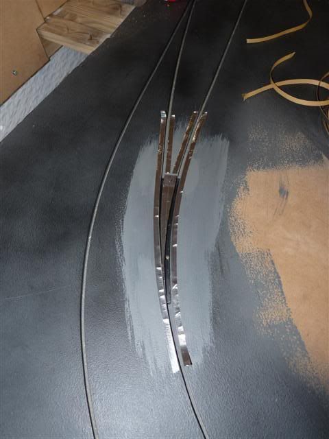
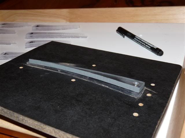
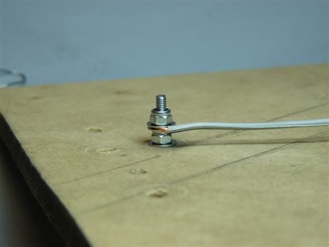
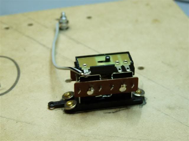
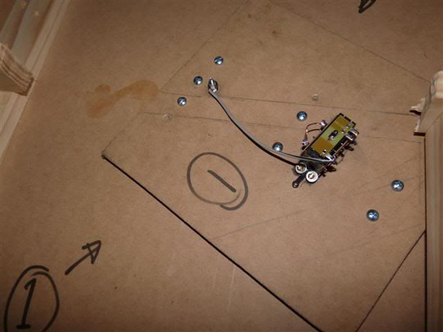
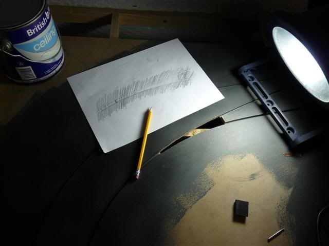
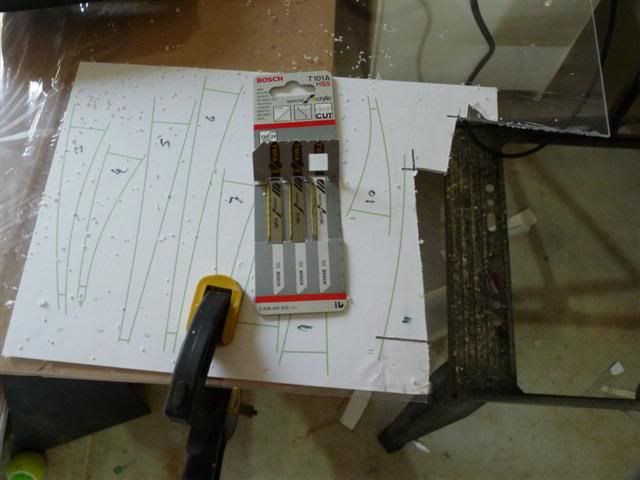
I ordered Luf's router kit and taping tool and started learning the craft on some test pieces. I have a background in electronics so have been playing around in that area too, decoding the Ninco protocols and building my own lane changers, but more of that in the future, I have to build a real track first.
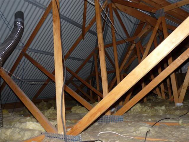
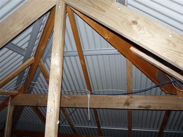
That's when I struck my first problem, where to put the track? The only way was up, into the roof, but this is what my attic looked like, a high pitched truss roof. Plenty of head room, but you couldn't move around for the trusses.
![Image]()
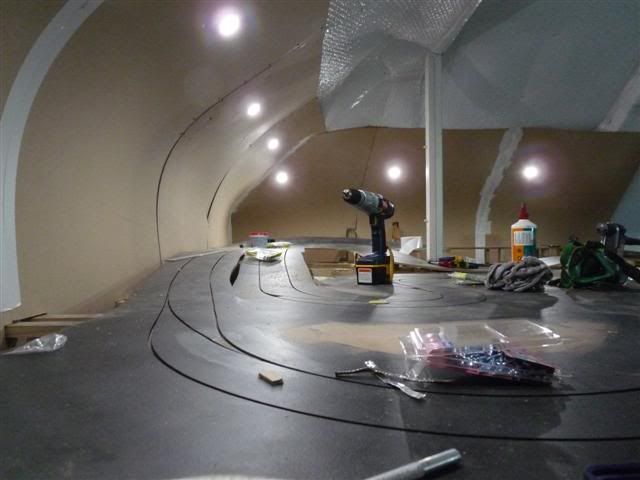
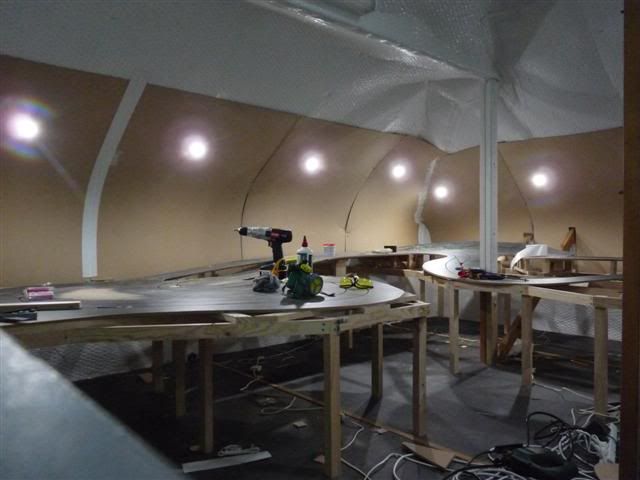
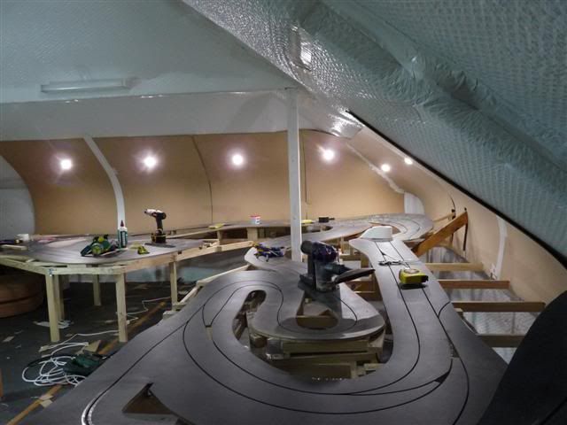
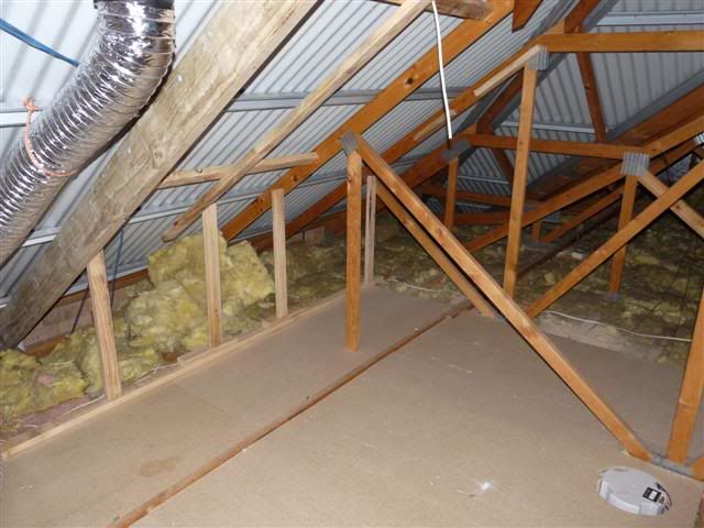
I decided to contact some experts, "Roof Access Systems" in Perth, very helpful. They organised an engineers report and were able to reinforce the roof and remove a number of the trusses, I was in business. They then wnet on to convert the space into something usable with floor, insulation for walls and a vent/skylight.
![Image]()
![Image]()
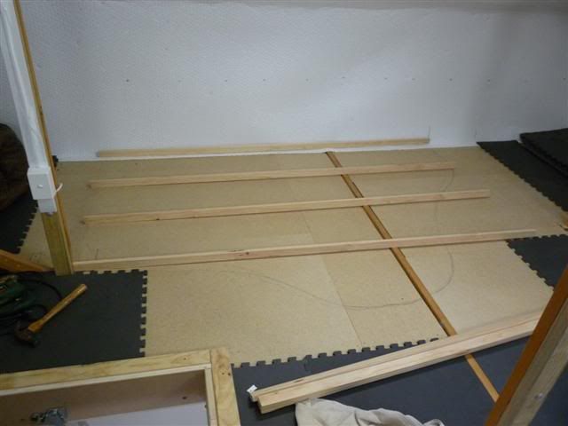
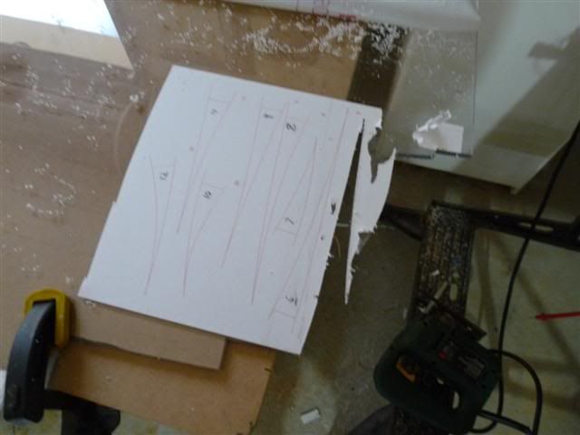
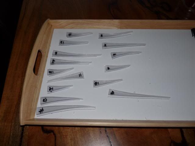
and now my work begins
![Image]()
Enjoyed it and watched the series TV series "Short Circuits", started looking at these web sites and then bang, I was bitten, I'm sure you know how it goes!
I was incredibly inspired by the works of jmswms, Luf and jmghF1.
I ordered Luf's router kit and taping tool and started learning the craft on some test pieces. I have a background in electronics so have been playing around in that area too, decoding the Ninco protocols and building my own lane changers, but more of that in the future, I have to build a real track first.
That's when I struck my first problem, where to put the track? The only way was up, into the roof, but this is what my attic looked like, a high pitched truss roof. Plenty of head room, but you couldn't move around for the trusses.
I decided to contact some experts, "Roof Access Systems" in Perth, very helpful. They organised an engineers report and were able to reinforce the roof and remove a number of the trusses, I was in business. They then wnet on to convert the space into something usable with floor, insulation for walls and a vent/skylight.
and now my work begins